USMI

Информация о пользователе

Привет, Гость! Войдите или зарегистрируйтесь.


Вы здесь » USMI » MCU, SoC, CPU Микроконтроллеры » JL SoC. 杰理芯片


JL SoC. 杰理芯片

Сообщений 1101 страница 1120 из 1317

1101

wy написал(а):

Мой вопрос: можно ли запрограммировать AC6969A2 на случайный выбор другого адреса Bluetooth при каждом запуске?

Не совсем понятно что имеется в виду. Автоподключение после включения ? Можно сделать автоподключение  к свободным устройствам или к заданным именам/адресам.

mezsvg написал(а):

Всем доброго времени суток, помогите с прошивкой МК AS21bp не могу понять даже как перевести его в режим работы по USB, хотя загрузил на плату ардуино скетч, подключил МК, но ничего не происходит

mezsvg написал(а):

Если я не ошибаюсь то МК AS21bp это ac6955f

Привет. Добро пожаловать. Покажи фотку лучше. Нужен конец маркировки а не начало.

Подпись автора

By Admin

1102

BIOS написал(а):

Привет. Добро пожаловать. Покажи фотку лучше. Нужен конец маркировки а не начало.

Вот фотографии
https://forumupload.ru/uploads/001b/ca/ … 439711.jpg
https://forumupload.ru/uploads/001b/ca/ … 129290.jpg

Такойже МК есть на плате https://electropeak.com/mh-m38-bluetoot … ver-module

1103

mezsvg написал(а):

Вот фотографии
https://forumupload.ru/uploads/001b/ca/ … 439711.jpg
https://forumupload.ru/uploads/001b/ca/ … 129290.jpg

Такойже МК есть на плате https://electropeak.com/mh-m38-bluetoot … ver-module

Вы правы, это действительно AC6955F. Глядя на ваше подключение, оно также выглядит правильным. Возможно, вы можете попробовать измерить мультиметром, чтобы убедиться, что контакты USBDP и USBDM не закорочены на землю на печатной плате.

Подпись автора

😊

1104

BIOS написал(а):

Не совсем понятно что имеется в виду. Автоподключение после включения ? Можно сделать автоподключение  к свободным устройствам или к заданным именам/адресам.

Прошу прощения за путаницу. Моя ситуация такова: у меня есть несколько устройств, которые ранее подключались к моему AC6969A2. Когда AC6969A2 включен, все устройства будут соревноваться за автоматическое подключение к AC6969A2. Мне интересно, есть ли способ для AC6969A2 генерировать новый адрес Bluetooth каждый раз, когда он включается, чтобы устройствам приходилось каждый раз повторно подключаться вручную. У меня нет контроля над внешними устройствами, поэтому мой единственный вариант - изменить встроенное ПО AC6969A2.

Подпись автора

😊

1105

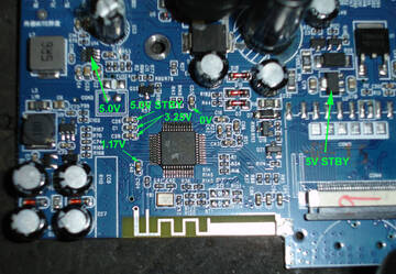
Помогите опозна чип.
Маркировка AC21BP02486[дальше затерто] так понимаю ничего не дает.
Из того что известно:
Pin 2   - 5V
Pin 3,4 - 3,25V
Pin 11  - 1,17V
Pin 38  - 0V
Pin 14,15 - Crystal 24 MHz
Pin 12  - BlueTooth

Смущает напряжение на выводах 11 и 38.

https://forumupload.ru/uploads/001b/ca/8a/102/t998413.jpg

1106

Совпадает только с AC6951C

Подпись автора

By Admin

1107

Hi

Iam trying to add my own c files into the sdk source.

For that, I have some doubts regarding this, i.e.

void main(u32 cfg_addr, u32 addr, u32 res, u32 first_start_flag)
{
    static u8 cnt = 0;
    board_main(cfg_addr,  addr, res, first_start_flag);

    puts("task_run\n");
#if POWERUP_DEV_IGNORE
    task_switch(TASK_ID_BT, NULL);
#else
    task_switch(TASK_ID_IDLE, IDLE_POWER_UP);
#endif
    /* task_switch(TASK_ID_ECHO, NULL); */
    /* task_switch(TASK_ID_RTC, NULL); */
    /* task_switch(TASK_ID_FM, NULL); */
    /* task_switch(TASK_ID_MUSIC, NULL); */
    /* task_switch(TASK_ID_LINEIN, NULL); */
    while (1) {

         
        task_manager();

    }
}

The above snippet is from the main file of the SDK. My doubt is where I need to call my own C file functions in the main? Do I need to create a separate task for that?

If you don't mind, could you please help me? It would be better for me

1108

Задачу создавать не обязательно. Я вообще не знаю как ее создать. Обращаюсь к функциям в своих файлах по тикам системного таймера. Вот так приблизительно:

Код:
const struct loop_detect_handler delay_1s ;
LOOP_DETECT_REGISTER(delay_1s ) =
{
    .time = 500,
    .fun  = delay_1s_count,
};

При  .time = 500 период вызова функции delay_1s_count(viod) будет равен 1 секунде. При .time = 1 период будет 2 ms. В общем случае период равен .time * 2 ms. Из функции delay_1s_count(viod) вызываю другие необходимые функции.

Первоначальную инициализацию в своих файлах разумно будет производить в самом низу файла cpu\board_init.c, в функции board_init(). Я оттуда вызываю свои функции инициализации.

1109

Alcest написал(а):

It is not necessary to create a task. I don't even know how to create it. I access the functions in my files by system timer ticks. Approximately like this:

With .time = 500, the delay_1s_count(viod) function call period will be equal to 1 second. With .time = 1 the period will be 2 ms. In general, the period is .time * 2 ms. From the delay_1s_count(viod) function I call other necessary functions.

It would be reasonable to perform the initial initialization in your files at the very bottom of the cpu\board_init.c file, in the board_init() function. I call my initialization functions from there.

Hi.

Where i put this handler in my code ?

1110

Вставьте В ЛЮБОЕ МЕСТО в своем файле.

Отредактировано Alcest (2024-01-28 20:56:22)

1111

Hi
How does the AC6082A in boot?
When I connect with Arduino , I receive a message(USB device not recognized)
Has this problem been solved?
this chip go into bootloader?

1112

Oh yes, I encountered this too. In fact, this is a 695 series of chip, but with a non-working part of Bluetooth, and a small amount of flash memory.
The problem is that there is no quartz crystal.
And all factory chips are flashed through ISP, in order for the chip to be clocked from the computer’s USB bus (or from a dongle, most likely) - you need to flash the fusebit through a special programmer.
LC-Trimm Fuse. But we can't use them yet.

Подпись автора

By Admin

1113

BIOS написал(а):

Oh yes, I encountered this too. In fact, this is a 695 series of chip, but with a non-working part of Bluetooth, and a small amount of flash memory.
The problem is that there is no quartz crystal.
And all factory chips are flashed through ESPI, in order for the chip to be clocked from the computer's USB bus (or from a dongle, most likely) - you need to flash the fusebit through a special programmer.
LC-Trimm Fuse. But we can't use them yet.

So with your orders, we can't access the dump at the moment.
I didn't see the crystal on the board, but I wanted to try my luck🙃
According to the datasheet of the chip, it lacks an external crystal. The board related to the programmable led RGB ( WS2812 ).
I am disappointed now😑

1114

In this case you need to enter the USB bootloader via an "ISP key", which uploads a small blob into chip that initializes its LRC oscillator and enters the USB bootloader itself.
In regard to the LC trim fuses, in your case they're probably being already programmed, as you seem to have a premade board rather than a bare chip that came right from factory.

Подпись автора

水Mizu-DEC JLtech since 22.06.2019

1115

На готовых платах тоже не работает , точнее в режиме аудиокарты работает, а вот когда перезагружаешься в бут то он не может тактироваться, дело в том что бутлоадер не может тактироваться от внутреннего генератора.

Подпись автора

By Admin

1116

И на готовых платах не прошит этот фьюз, потому что для готовых плат они заливают софт через ISP прогер массово, и соответственно у ISP (spi) свое внешнее тактирование.

Подпись автора

By Admin

1117

Для начала думаю надо начать с простого, через ISP считать ID чипа и узнать чем он всё таки является, ну и будет ли это работать вообще.
Загружаем этот скетч и подключаем чип к нужным пинам - здесь pin11 это ISP_CLK (D+), pin12 это ISP_DIN (D-), а pin10 это ключ по питанию.
Открываем монитор порта, и смотрим: если чип смог перейти в ISP, то туда будут печататься строки вроде "Got the chip ID: 5F/A4", где '5F' это сам ID чипа, для справки: 5E это BR23, 5F это BR25.

Код:
#define POWER_CTL      10  // Power switch
#define JL_CLK         11  // goes to USBDP
#define JL_DAT         12  // goes to USBDM

/*========================================================*/

bool powered_on;

void power_off(void) {
  digitalWrite(POWER_CTL, LOW);
  powered_on = false;
}

void power_on(void) {
  if (powered_on) {
    power_off();
    delay(100);
  }

  digitalWrite(POWER_CTL, HIGH);
  powered_on = true;
}

/*========================================================*/

enum {
  ISP_CMD_READ_BUFF     = 0x07, // Read temp buffer
  ISP_CMD_RAM_NEXT      = 0x12, // Advance to a next RAM word
  ISP_CMD_ECHO          = 0x14, // Echo back
  ISP_CMD_RAM_WRITE     = 0x18, // Write a word into RAM
  ISP_CMD_START_CPU     = 0x19, // Start the CPU
  ISP_CMD_CHIP_ID2      = 0x1E, // Read another chip ID (minor?)
  ISP_CMD_CHIP_ID       = 0x1F, // Read chip ID (major?)
};


void isp_init(void) {
  digitalWrite(JL_CLK, LOW);
  pinMode(JL_CLK, OUTPUT);
  pinMode(JL_DAT, INPUT);
}

void isp_deinit(void) {
  pinMode(JL_CLK, INPUT);
  pinMode(JL_DAT, INPUT);
}

void isp_sendb(uint8_t val) {
  pinMode(JL_DAT, OUTPUT);

  for (uint8_t mask = 0x80; mask; mask >>= 1) {
    digitalWrite(JL_DAT, val & mask ? HIGH:LOW);
    digitalWrite(JL_CLK, HIGH);
    delayMicroseconds(5);
    digitalWrite(JL_CLK, LOW);
    delayMicroseconds(5);
  }
}

uint8_t isp_recvb() {
  uint8_t val = 0;
  
  pinMode(JL_DAT, INPUT);

  for (uint8_t mask = 0x80; mask; mask >>= 1) {
    digitalWrite(JL_CLK, HIGH);
    delayMicroseconds(5);
    digitalWrite(JL_CLK, LOW);
    if (digitalRead(JL_DAT)) val |= mask;
    delayMicroseconds(5);
  }

  return val;
}

/*
 * MODE_DET key for entering the ISP mode
 */
void isp_modedet_key(char type) {
  isp_sendb(0xFF);

  switch (type) {
  case 0: isp_sendb(0x6A); isp_sendb(0x58);                  break;  // 6A58    - BR17 and older
  case 1: isp_sendb(0x81); isp_sendb(0xF9); isp_sendb(0xA8); break;  // 81F9A8  - BR20
  case 2: isp_sendb(0x01); isp_sendb(0xF9); isp_sendb(0xA8); break;  // 01F9A8  - BR21 and newer
  }
}

/*
 * An ISP init sequence
 */
void isp_initseq() {
  isp_sendb(0x00);
  isp_sendb(0x00);
  isp_sendb(0x00);
  isp_sendb(0x00);
  isp_sendb(0x00);
  isp_sendb(0xA8);
  isp_sendb(0x00);
  isp_sendb(0x00);
}

/*
 * Basic commands (taking no data)
 */
void isp_cmd_exec(char op) {
  /* Ooooo... ........ */
  isp_sendb(op << 3);
  isp_sendb(0);
}

/*
 * 1-byte operand/response commands
 */
void isp_cmd_send1(char op, uint8_t val) {
  /* OooooVvv vvvvv... */
  isp_sendb((op << 3) | (val >> 5));
  isp_sendb(val << 3);
}

/*
 * 4-byte operand/response commands
 */
uint32_t isp_cmd_recv4(char op) {
  /* Ooooo... | Aaaaaaaa Bbbbbbbb Cccccccc Dddddddd */
  uint32_t tmp;
  isp_sendb(op << 3);
  tmp  = (long)isp_recvb() << 24;
  tmp |= (long)isp_recvb() << 16;
  tmp |= (long)isp_recvb() << 8;
  tmp |= (long)isp_recvb() << 0;
  return tmp;
}

/*========================================================*/

void setup() {
  digitalWrite(POWER_CTL, LOW);
  pinMode(POWER_CTL, OUTPUT);
  pinMode(JL_CLK, INPUT);
  pinMode(JL_DAT, INPUT);

  Serial.begin(19200);
}

void loop() {
  power_on();
  isp_init();

  for (int i = 0; i < 10; i++) {
    isp_modedet_key(2);
    isp_initseq();

    uint32_t recv;

    isp_cmd_exec(ISP_CMD_CHIP_ID);
    recv = isp_cmd_recv4(ISP_CMD_READ_BUFF);

    if ((recv & ~0xFF) == 0 && (recv & 0xFF) != 0) {
      Serial.print("Got the chip ID: ");
      Serial.print(recv, HEX);

      Serial.print('/');

      isp_cmd_exec(ISP_CMD_CHIP_ID2);
      recv = isp_cmd_recv4(ISP_CMD_READ_BUFF);
      Serial.println(recv, HEX);
      break;
    }
  }

  isp_deinit();
}
Подпись автора

水Mizu-DEC JLtech since 22.06.2019

1118

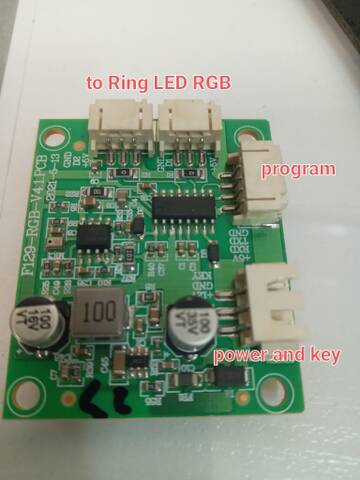
https://forumupload.ru/uploads/001b/ca/8a/87/t406954.jpg

1119

Thank you. That right. In fact, this board receives the sound from the speaker through the microphone and the lighting is done according to the volume of the sound.
which is produced by a mic and LM358, a buck converter and an ac6082A (number has been erased). It was produced in the factory

1120

kagaimiq написал(а):

To begin with, I think we need to start with something simple, read the ID of the chip through the ISP and find out what it is, and whether it will work at all.
Load this sketch and connect the chip to the required pins - here pin11 is ISP_CLK (D+), pin12 is ISP_DIN (D-), and pin10 is the power switch.
We open the port monitor and look: if the chip was able to go to the ISP, then lines like "Got the chip ID: 5F/A4" will be printed there, where '5F' is the chip ID itself, for reference: 5E is BR23, 5F is BR25 .

Did this code work?


Вы здесь » USMI » MCU, SoC, CPU Микроконтроллеры » JL SoC. 杰理芯片